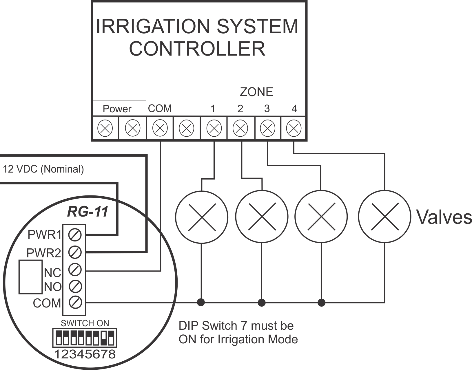
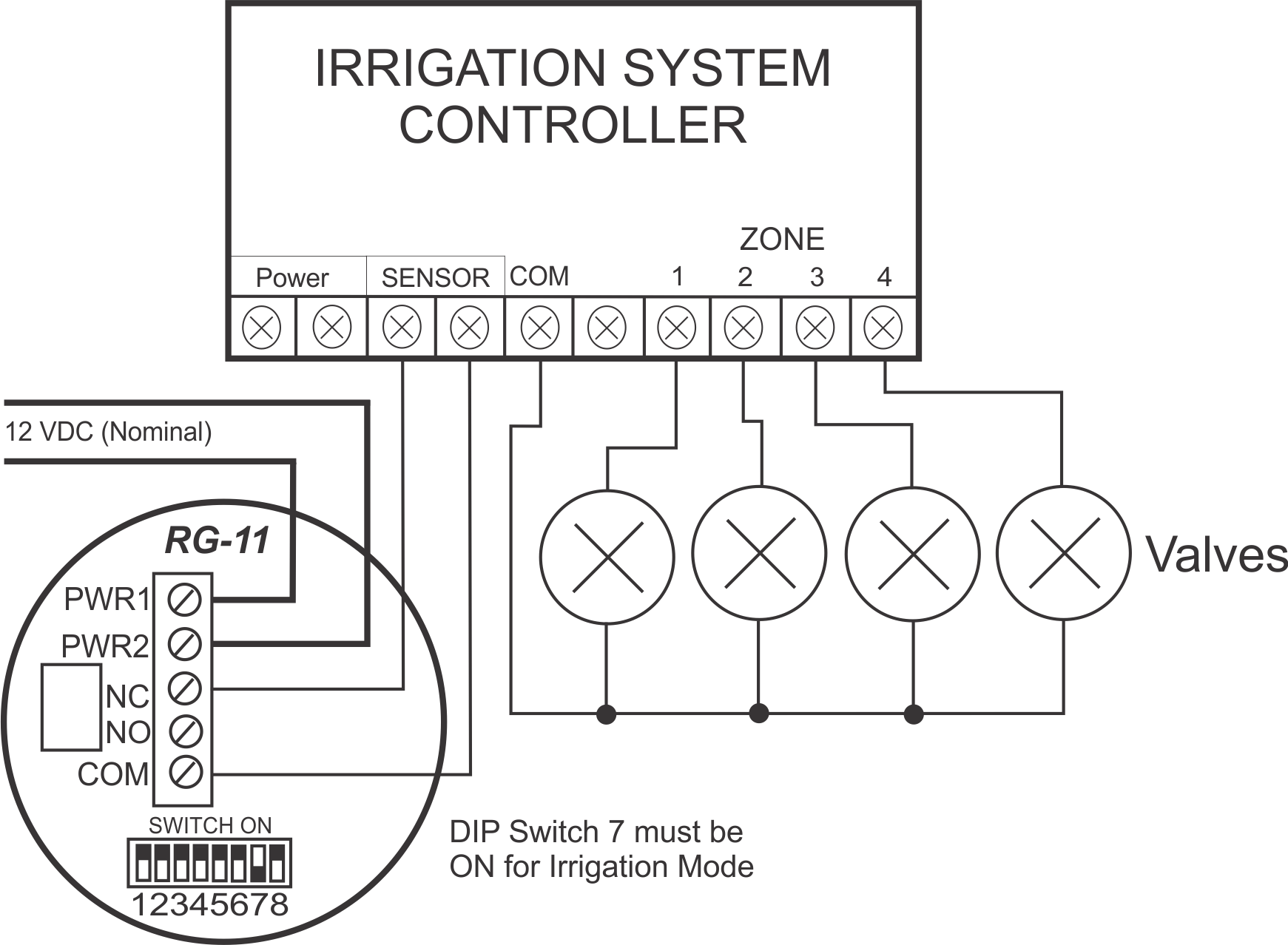
Typical Connection– Rain Sensor Interrupts Valves
In this irrigation setup, the RG-11 interrupts the flow of current to the zone valves when it needs to inhibit watering. When the rain amount hits the threshold, the relay opens the normally closed (NC) connection. When the rain has evaporated, the NC connection closes again, and the irrigation cycle resumes normal operation.
The RG-11 also requires a source of power, and may be powered from the transformer that powers the irrigation controller.


