The RG-9 and RG-15 share the same hardware but have significantly different firmware. The RG-9 is a Rain Detector and the RG-15 is designed as a Tipping Bucket Replacement. Both have an NPN Open Collector main output and bidirectional TTL Serial data communication mechanism.
Please note that many questions are also answered in the RG-9 Instruction Guide and the RG-15 Instruction Guide.
Electrical
Input Voltage Specifications
From the RG-9 and RG-15 Instruction Guides:
Range 5-35 VDC on J1 or J2P2
Reverse polarity protected to 50V.
A stable supply using star grounding techniques and dedicated wiring will provide the best results.
Alternative
3.3V though pin 8 on J2. Note if this isn’t an ultra stable supply it will induce false indications. An overvoltage to this pin will destroy the device. For most, avoid this solution.
The alternative, while on the surface looks appealing, particularly since it looks like it can be powered by a 3.3v supply from an Arduino or ESP32, the problem is that these sources are often quite noisy. This connection bypasses the internal Low Dropout Regulator and injects power directly into the device. While we do have customers who have been able to successfully make this connection, it is not trivial in any circumstance and particular if you are not using rock solid clean power.
Connecting to the J2 Connector
Ribbon style: Amphenol 71600-008LF available from DigiKey will work especially with ribbon cable, although if you are careful, regular cable can be attached. Good for low profile work, such as in the RG-15. We use this all the time.
Discrete: Tight fit. Discrete connector socket: Molex 0022566087 and gold crimp Molex 0016020103 or tin crimp Molex 0016020086. For a slightly lower profile: socket Harwin M20-1070400 and gold crimp Harwin M20-1180042 or tin crimp Harwin M20-1180046
What kind of output does the RG-9 and RG-15 have?
The main output is NPN Transistor Collector, commonly known as an Open Collector. When the output is activated (will differ on when this is done for the RG-9 and RG-15) the collector is pulled low and whatever load resistor is connected will also be pulled low. The specifications for the collector are: 500 mA / 80V / 300mW Max. The beauty of an open collector system is that it can be used for level translation. The internals of the RG-9 and RG-15 are 3.3VDC. You are not restricted to that range with the open collector. The only requirement is that the ground is common.
My application is solar powered. Can I use the RG-9 or RG-15 Rain Sensor?
Yes! The normal current drain of the RG-9 and RG-15 is 110 uA. This is under no-rain conditions, starting about 20 minutes after the last rain drop is detected. Otherwise the current consumption is under 2 mA. You want to keep the load current down on the Open Collector to keep this condition.
RG-15 Low Power Operation and Serial Communication.
Using serial communication and the lowest possible power from the sensor requires a different path.
How you talk to the RG-15 will be important. Our blog entry: How to use a RG-15 with a standard RS232 system utilizes the MAX3232 level translator. The RG-15 monitors pin 5 (RS232 IN) and inhibits sleep if there is a + voltage on it. This is the default condition for the MAX3232 communication. So if you are using this system, the RG-15 will not sleep. This section will refer to other UART connections, such as with an ESP32 or Arduino, which is mentioned in our RG Arduino Guide.
If you disable the UART connected to the RG-15, it will power down after 20 minutes after the last rain drop detected. You can poll for information. Unfortunately, each time this is done, the 20 minute clock will restart. It appears a good way to manage power is to have the RG-15 tell you that it is raining. This can be done using the Open Collector output as an interrupt. When it is raining, the RG-15 will remain running at the 2mA range and the tipping bucket output will be triggered for each increment detected (low or high resolution). Once you know it is running, you can query the serial port to see what has happened…
How do I connect an external tipping bucket to the RG-15?
Most tipping buckets utilize a reed switch that momentarily closes for each tipping bucket event. Verify that the TB is equipped with this component. If not, please contact us at info@rainsensors.com for guidance.
Connect a tipping bucket as an external input to the RG-15: Connect the two external tipping bucket outputs to the RG-15 tipping bucket input (TB IN: J2P6) & ground (GND: J2P1 or J1 GND) using 2 conductor 18 gauge zip cord (or equivalent).
To minimize input noise that may be injected on the line to the RG-15, a 3.3k – 10 k ohm pull-up resistor can be added from J2P6 to the RG-15 3.3v regulator, J2P8.
To enable the External Tipping Bucket data stream via the serial data connection, send the command “X”. The “Y” command disables the external tipping bucket data stream.
Mechanical
What material is the RG-9 and RG-15 made of?
The lens is made of UV stabilized polycarbonate, the case is made of UV stabilized ABS, the screws are stainless steel and the o-ring is silicone.
The O-ring doesn’t fit properly, it’s seems to be too small.
Try stretching it a before putting it into the groove. This will help to expand the O-ring for a bit while you assemble the RG-9/RG-15 Rain Gauge. It is best to stretch it enough so it becomes “too big” to fit in the groove. After the Rain Sensor has been in operation and assembled for some time, the O-ring tends to stay in place when the RG-9/RG-15 is disassembled. But if it falls out again, just stretch the O-ring before assembly.
What is the IP rating (waterproofing) for the RG’s?
The IP rating of the sensor is a bit tricky. The unit should easily reach IP55 using general careful assembly techniques. The O-ring must be properly seated. The unit can function without, but the silicone rubber gasket is hydrophobic and minimizes/eliminates possible capillary action.
If the cable gland is tightly closed around the properly sized round cable, the rating can be IP66. Since we do not control the final connections, it is difficult to definitively show any rating.
Some of our customers fabricate their own housing to mate with the lens. In that case, there may be no cable gland to get in the way and you should easily get an IP67 rating… we have quite a few on yachts for their windshield wiper control systems.
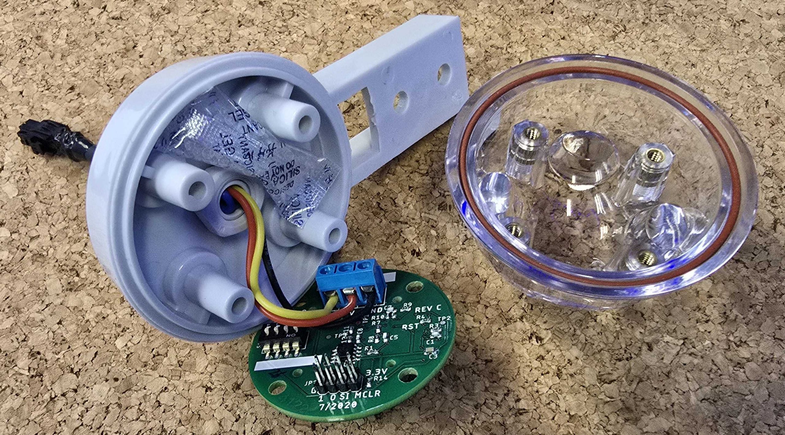
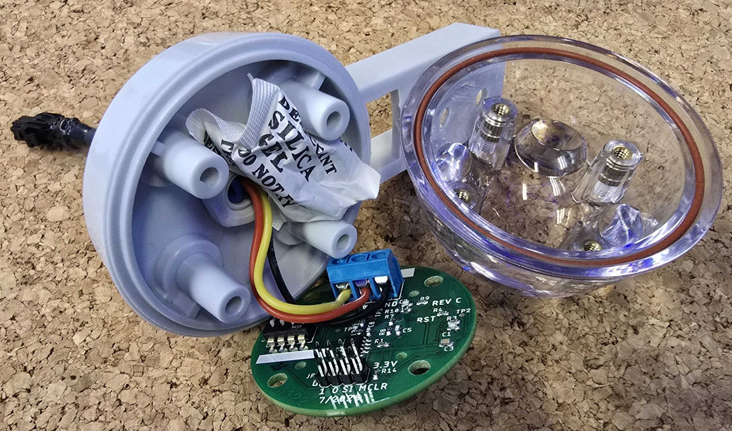
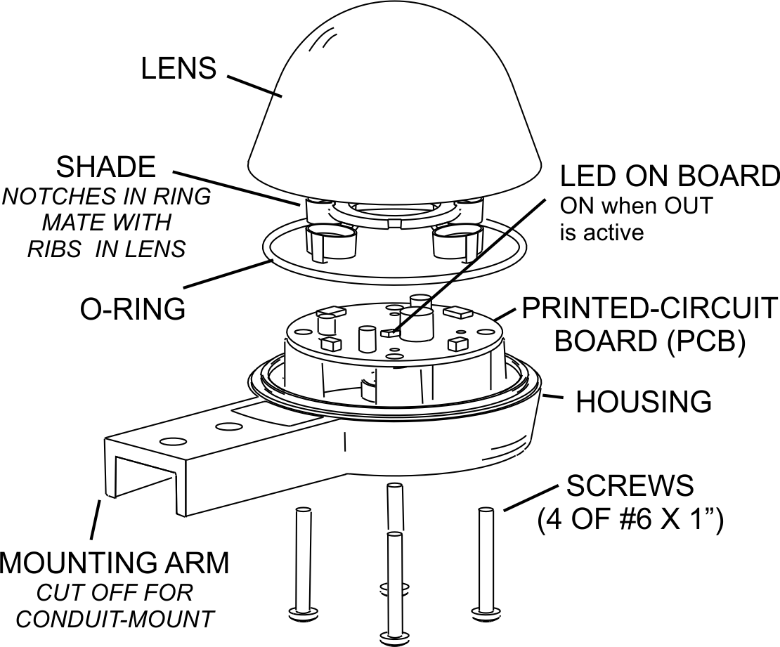
What is the small bag in the RG sensor and what is the proper way to assemble the sensor?
The small bag is a silica gel pack and is an integral component for moisture management in the RG sensor. The sensor is properly sealed when the O-ring is properly placed, the cable gland is well clamped on the round jacketed multiple conductor cable exiting the housing and is tightened with the stainless steel screws. Tighten the screws using the torque adjusted screwdriver or equivalent to 1.1 Nm (0.8 lb-ft). This is light “hand tight” using a screwdriver.
The 2g silica gel pack is placed in the sealed and enclosed space. It is very effective as it is oversized for the enclosed space. It reduces the internal moisture well below the dew point so no condensation can be formed on the inside surface of the lens, which could trigger false positives.
There are two styles of silica gel pack, below shows how each of them should be placed. You want to be careful to not rupture the package by keeping it away from the 4 bosses where the screws go and the PC Board is retained. Also, stay away from the O-ring and the matching housing perimeter. This will also break the sensor seal.
Additionally, the PC Board is conformal coated, so should not be affected by residual moisture.
Serial Communication
Selected RG-15 Commands
A Response: Acc 0.000 in
Acc = Accumulation. The amount of accumulation detected since the last Acc message.
R Response: Acc 0.00 mm, EventAcc 0.00 mm, TotalAcc 0.00 mm, RInt 0.00 mmph or
Acc 0.00 in, EventAcc 0.00 in, TotalAcc 0.00 in, RInt 0.00 iph
Acc = Accumulation. The amount of accumulation detected since the last Acc message.
EventAcc = Event Accumulation. This is the amount of rain detected during the current rain event. This counter resets 60 minutes after the RG-15 has detected the last drop.
TotalAcc = Total Accumulation. This is the total amount of accumulation recorded since the device was last reset with the “o” command. The maximum value for TotalAcc is 65.535” before it rolls over.
Rint = Rain Intensity. This is calculated over the past minute and extrapolated to the hour.
See the RG-15 instruction guide for reference.
The “c” command is for continuous mode. When the RG-15 has something to say, it will say it.
The ”p” command, the RG-15 will not say anything unless spoken to, such as with the “a” or “r” command.
What are the R values from the RG-9 and what are the Sensitivity Levels?
The “R” values from the RG-9 are Rain Intensity values. The serial output of the RG-9 includes an R value command that displays the current Rain Intensity level. These values also correspond to the DIP switch settings for the trigger sensitivity and the “I” command for setting the trigger sensitivity levels.
See the RG-9 Instruction Guide for more information.
| Rain Intensity | in/h (Inches per hour) | mm/h (millimeters per hour) | Rain Characterization |
| R0 | 0.0 | 0.0 | None |
| R1 | 0.0+ | 0.0+ | Rain Drops |
| R2 | 0.01+ | 0.25+ | Very Light |
| R3 | 0.1+ | 2.5+ | Medium Light |
| R4 | 0.3+ | 8+ | Medium |
| R5 | 0.5+ | 13+ | Medium Heavy |
| R6 | 1.0+ | 25+ | Heavy |
| R7 | 2.0+ | 50+ | Violent |
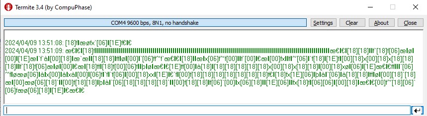
Help! I only get gibberish from the RG!
There is probably a mismatch between the terminal emulator (or equivalent) and the RG-9 or RG-15. Refer to the blog entry: How to use a RG-15 with a standard RS232 system on a way to communication with the RG-9 and RG-15.
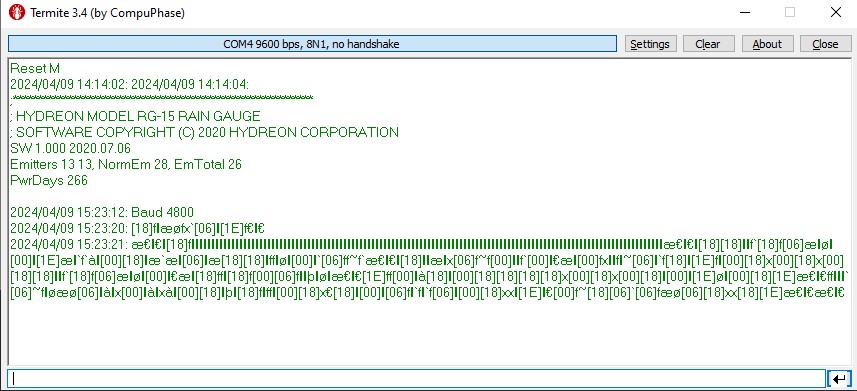
Unfortunately with a baud rate mismatch, telling the RG what baud rate to use may not go so well. The mis-timed data to the UART may not properly interpret the data sent to it. In his example the terminal emulator is set to 9600 baud and the RG-9 is set to 4800 baud. This is what it can look like:
Here are the baud rate options:
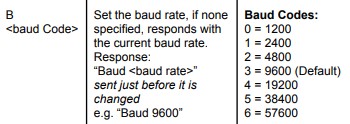
It may be best to set the terminal emulator (or equivalent) to each of the above rates and reset (MCLR to ground) or power cycle the RG to see if you have found the match. In this example, the terminal emulator has been set to 4800 baud.
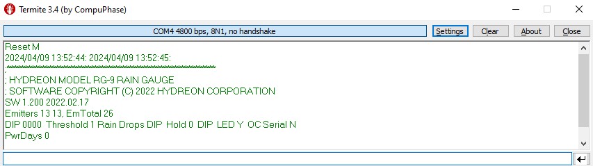
Alternately if you wish to change the baud rate of the RG-9 or RG-15, use the command b <baud rate code>. In this example both the terminal emulator and the RG-15 are set to 9600 baud and we want to set the RG-15 to 4800. Send the code b 2 to the RG. The code is recognized and the RG comes back with Baud 4800. A subsequent MCLR will result in something like this:
Now to see what the RG is communicating, change the terminal emulator to 4800 baud and do the MCLR again. It should look like the screen shot two images above. The good news is that there are only 7 alternatives, including the default 9600 baud.
Operational
Is there a way to test the RG-9 without waiting for it to rain or spray it with a hose or a squirt bottle?
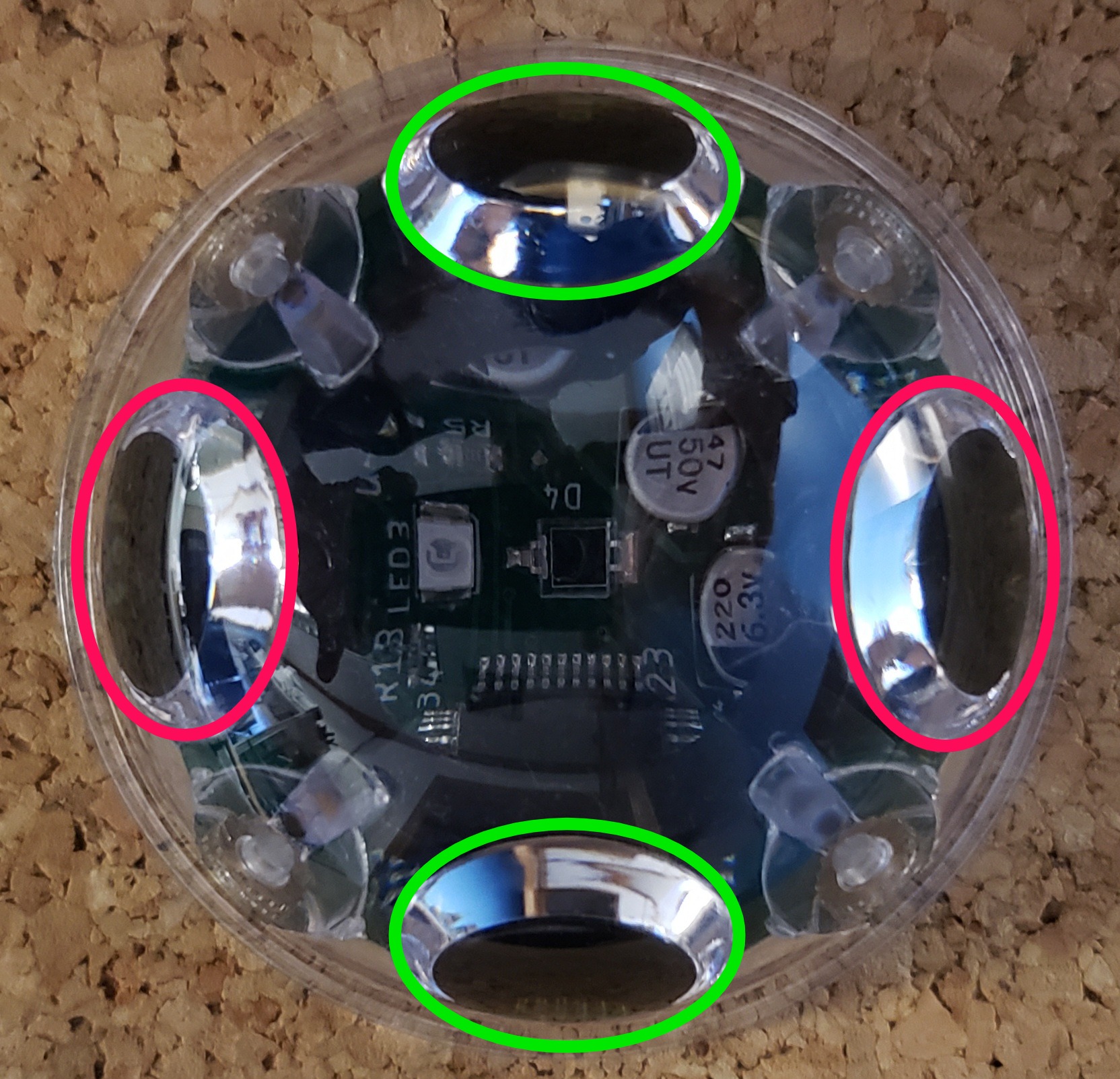
Yes! Set the DIP switches to Sensitivity 1 (Rain Drops) (the extend is not important here) and power the unit. Swipe your finger across one or more of the sensing areas (the infrared emitter/sensor pairs are shown in Red and Green) to simulate rain. Generally, you want a sensitive setting to keep from wearing out your finger in the process. The RG-9 will activate the green LED for a visible indicator and the NPN Open Collector output section will activate. They will remain activated until the decay time passes the threshold and the unit resets.
Is there a way to test the RG-15 without waiting for it to rain or spray it with a hose or a squirt bottle?
Yes! Set the DIP switch to high resolution (units are not important here) and power the unit. Swipe your finger across one or more of the sensing areas (the emitter/receiver pairs are shown in Red and Green) to simulate rain. Generally, you want a sensitive setting to keep from wearing out your finger in the process. The RG-15 will provide a light pulse and the NPN Open Collector output section will activate for a short while.
I want to know if I can get the RG-15 to tell me when it just starts raining and how much?
While the RG-11 and RG-9 may be better suited to handle this task, with the serial communication the RG-15 can tell when it is just starting to rain. Look for the “Event”. The Event starts when the RG-15 first detects rain
The RG-15 is not perfectly configured for what you ask, but a way to do what you ask is to look for “Event”, it will be just before the software revision and just after a comment line. Something like this:
;—————————————-
Event
SW 1.000 2020.07.06
This Event is when the RG-15 has an indication that there is precipitation. It may or may not be enough to trip the Accumulator threshold of 0.001” (or the mm equivalent)
To get the accumulation in 3 days, I would suggest using the TotalAcc value. This value continues until it is reset with the “o” command. The “k” command does not reset this counter.
R Response: Acc 0.00 mm, EventAcc 0.00 mm, TotalAcc 0.00 mm, RInt 0.00 mmph or
Acc 0.00 in, EventAcc 0.00 in, TotalAcc 0.00 in, RInt 0.00 iph
Acc = Accumulation. The amount of accumulation detected since the last Acc message.
EventAcc = Event Accumulation. This is the amount of rain detected during the current rain event. This counter resets 60 minutes after the RG-15 has detected the last drop.
TotalAcc = Total Accumulation. This is the total amount of accumulation recorded since the device was last reset with the “o” command.
Rint = Rain Intensity. This is calculated over the past minute and extrapolated to the hour.
See the RG-15 instruction guide for reference.
Troubleshooting
Troubleshooting RG-9 & RG-15 False Positives: Overview
False positives are an indication of rain when there does not appear to be any. Determining the cause of false positives is difficult. False positives have many possible root causes. There are generally two general areas we look for: Power and Optical
Troubleshooting RG-9 & RG-15 False Positives: Power Supply, standard connection
First is the power supply. We like to see a star style grounding and supply system and dedicated wiring to the sensor. We have also found that it should be a relatively stable supply. While the internal regulator is of high quality, we have found that very noisy power sources can still pass through enough noise to mess with the internal A/D circuitry that is detecting very small light intensity levels. Leave the sensor on it’s own cable and preferably do not allow other equipment to share the line where power supply fluctuations can be injected. Buck regulators generate significant noise and should also be avoided unless you are prepared to use 3rd order LC filters.
Troubleshooting RG-9 & RG-15 False Positives: 3.3V Direct Connect, bypassing the internal regulator
Attempting to directly power the internal circuity from the J2P8 connector is tempting since many applications connect our RG-9 or RG-15 sensors to controllers with 3.3V supplies. Extreme caution is necessary should you go down this path. The reason is the 3.3V tap bypasses the internal voltage regulator and subjects the circuit to noise on the 3.3V line. The A/D circuit is trying to detect microvolt level signals and we have found that it VERY easy to mess up, especially when run via the ESP32 or Arduino supplies. It is full of noise spikes and can easily render the sensor unusable. We do have a few customers that we have been able to get running with a 3.3v supply, but it was not easy and would often require 3rd order LC filters to work. So if you have an alternative supply, at least for starters, try that.
We strongly suggest that you use the standard voltage input of 5 – 35VDC to V+ on J1 or J2P2.
Troubleshooting RG-9 & RG-15 False Positives: Optical Overview
The second area is optically related. There are several subcategories here.
We have found that pulsing shade, say from a rotating anemometer or blowing leaves can cause problem. A second optical area is in sealing the sensor assembly. We have found that at times the O-Ring and/or the silica gel packet were not installed. This results in internal moisture that can condense as the sun heats the assembly and the moisture has no place to go. That results in false positives
Troubleshooting RG-9 & RG-15 False Positives: Optical, Pulsing Shade
The second area is optically related. There are several subcategories here.
We have found that pulsing shade, say from a rotating anemometer or blowing leaves can cause problem.
The ideal guidance is to have the no obstructions between or around the sensor and the sun. If that is not possible, as with the rotating anemometer above, an optical shield may be necessary.
We have also received some reports where during a particular time of day false positives will occur. If you have one of these conditions, try to position yourself in the position of the sensor and look to see what may be causing the light intensity to change rapidly.
Troubleshooting RG-9 & RG-15 False Positives: Optical Assembly, Sealing
A second optical area is in sealing the sensor assembly. We have found that at times the O-Ring and/or the silica gel packet were not installed or the assembly was not properly assembled. Thermal transitions in high humidity areas often result in internal moisture condensing as the internal temperature drops below the localized dew point within the assembly. The moisture has no place to go and condenses on the inside of the lens. Depending on how fast this happens, it can result in false positives. Make sure the O-ring is properly placed in the track of the housing, the cable gland is firmly clamped around a ROUND Cable and the silica gel pack is in place in the area be tween the board and housing. See the diagram below (still needs work).
Other
Why no phone number for technical support?
We have found that most of our communication is with highly skilled embedded systems engineers. They require finely detailed responses with documentation and support as they seek to get our sensors working optimally in their system. We have found that nearly all the hobbyists fall into the same category.
That is why we use email exclusively. We seek to minimize miscommunication.
Can I contact you if I have more questions?
Of Course! Email us at info@hydreon.com.