This example shows how you can convert the Serial TTL 3.3V output of the RG-15 to standard RS232(TIA232). This will allow us to both receive the data from the device as well as send commands to configure it. To accomplish this we need a TI-MAX3232, but to make this easier we used a board that already had the connections we needed to make this as plug and play as possible.
Hardware Required
- RG-15 – store.hydreon.com
- RS232 to TLL conversion board that uses a MAX3232 – Amazon
- USB to RS232 Adapter cable (If wanting to connect to a computer) – Amazon
Powering the Conversion board
In this case we powered the conversion board though a 9v DC supply. In the case of our conversion board it doesn’t take that much power, we measured it at about 7mA. This falls well within what the RG-15 can supply to the 3.3v pin of about 45mA. If what you are trying to power has a peak requirement of above that 45mA you cannot power it from the RG-15.
Cabling
Since the TTL conversion board doesn’t fit within the housing of the RG-15, we opted to put it inside the building with our other equipment. We used a 8 core stranded 22 AWG cable in our installation running it about 8ft, but we also tried the longest 21ft Cat5e cable we had and found it to be working at 9600 baud. We have not tested this longer distances though, they may not work reliably.
If using Cat5e
Tie all the ground together at the RG-15 side. When using the TB output use the ground use the Green/White GND To try and minimize interference we wired it using:
- Orange/White – GND (Unconnected on adapter side)
- Orange – SO – TXD
- Green/White – GND (Use for TB output GND)
- Green – SI – RXD
- Blue – O(TB Out)
- Blue/White – 3.3V – Vcc
- Brown – V+
- Brown/White – GND (Use for PSU GND)
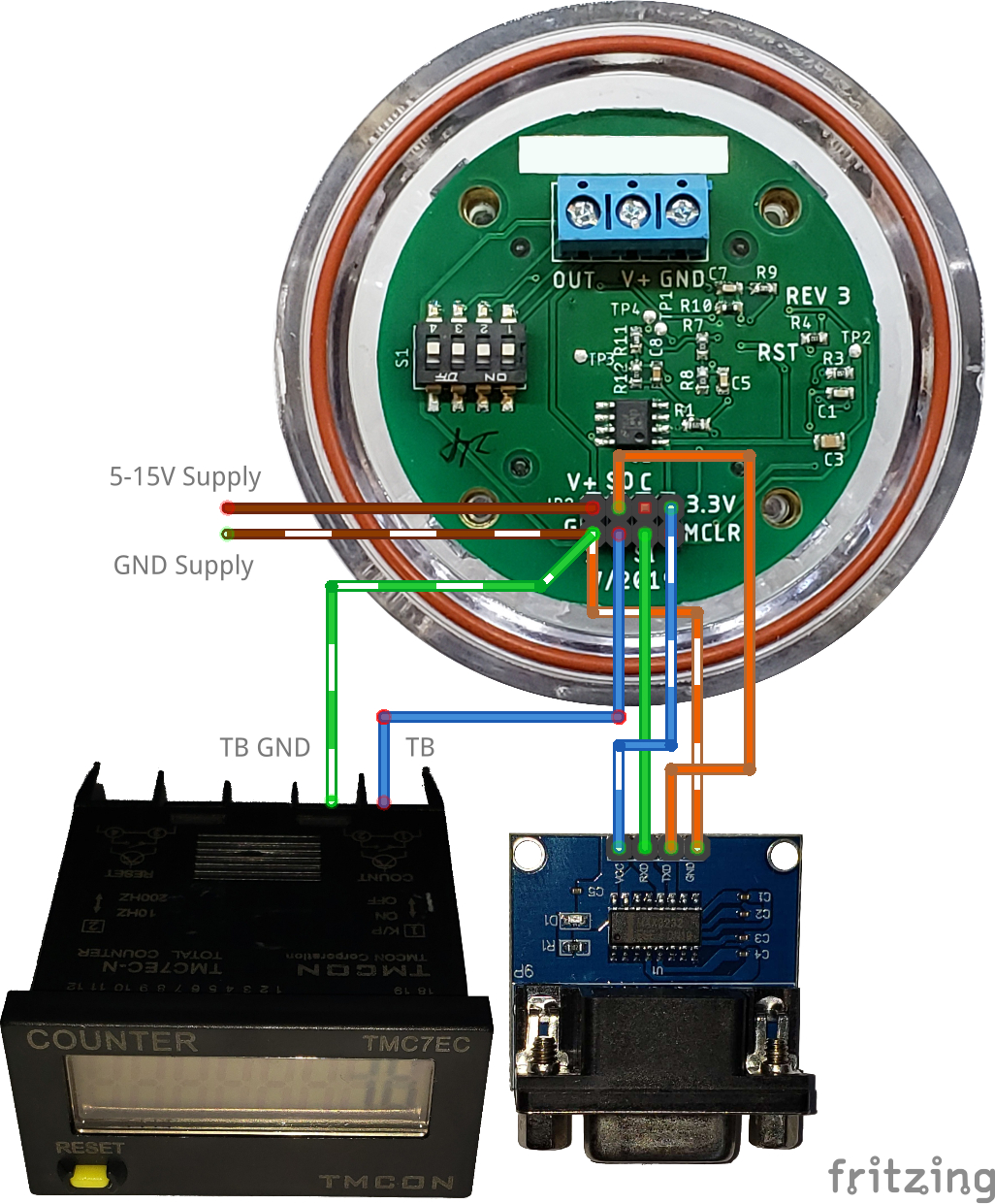
Wiring the device
Connect the Vcc on the conversion board to the J2 V+ and the GND to the J2 GND. For connection communication connect the J2-SO(Serial out) to TXD and the J2-SI(Serial in) to RXD on the converter. Now just plug your USB to RS232 cable into the converter and your computer.
Usage
Everything is now setup to communicate with the device, you are able to send commands and read the output of the device. The most recent documentation on the commands and communication protocol can be found in the RG-15 Instructions.
Connecting to a computer
Once everything is setup all you need is a program to communicate with the device, for Windows we like to use Termite. While this isn’t the only software available we like since it has features such as adding timestamps to the data and logging directly to a file. Assuming you don’t have any other serial devices connected to your computer Termite should automatically select this device for you. You just need to change the baud rate used for this device in the Settings menu, the default used for the RG-15 is 9600. If you run into issues open up Device Manager and look at the Ports section, any plugged in serial devices should appear here. If have multiple shown try plugging and unplugging the cable and see which device appears and disappears noting its COM id. Make sure this COM id is selected in Termite under the settings menu. Also from here you can enable the extra features for timestamping lines and logging to a file. (If these plugins don’t show up you completed a minimal installation of Termite, try reinstalling and making sure they are selected)
Connection issues
If you experience issues with the serial device disconnecting or stops responding in Windows try changing your power management settings to prevent the internal usb hub from turning off. If you are still having issues and are using an external usb hub, we have noticed switching to a different higher quality usb hub has fixed the issue for us.