Example responses
Acc 0.001 in, EventAcc 0.002 in, TotalAcc 0.003 in, RInt 0.082 iph
Acc 0.001 in, EventAcc 0.002 in, TotalAcc 0.003 in, RInt 0.004 iph, XTBTips 0, XTBAcc 0.01 in, XTBEventAcc 0.02 in, XTBTotalAcc 0.03 in
Hardware Required
- RG-15 – store.hydreon.com
- Arduino Board (Uno) – Arduino Products
- Ethernet Shield – Amazon
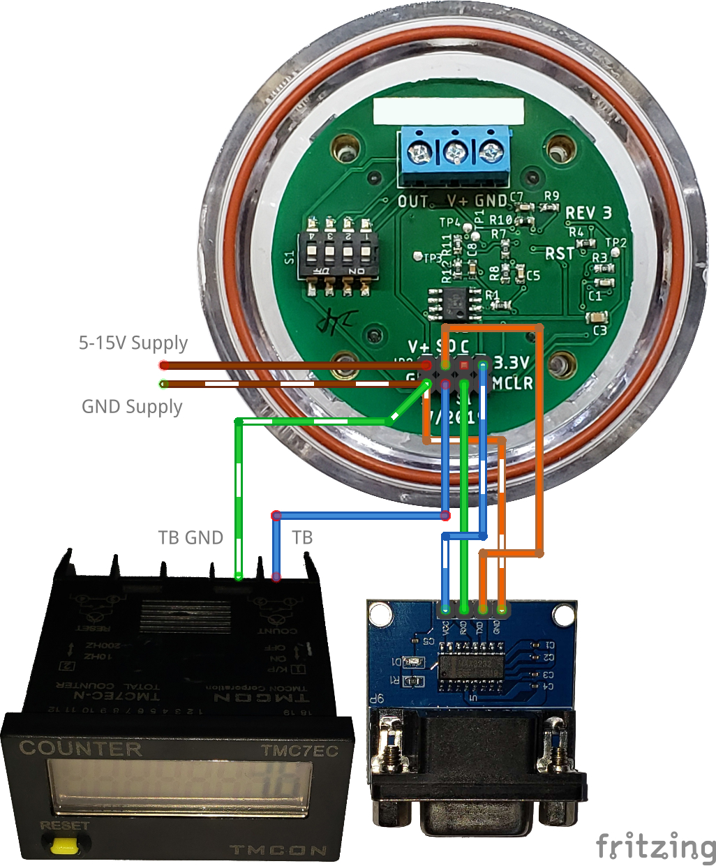
Cabling
When running this at a distance we recommend you follow the cabling section on our recent post How to use a RG-15 with a standard RS232 systemWiring
Most ethernet shields use pins 10-13 to communicate, so we need to select one that isn’t used to communicate with the RG-15. For this we used pins 5 & 6, if your ethernet hat uses these pins make sure to select different ones in the editor. Note: this only applies if you are using an arduino that doesn’t have a second hardware serial. If your device has this make sure to use the TX1 & RX1 pins instead. After equipping the ethernet shield, connect the SO(Serial out) pin to pin 5 on the shield to the SI(Serial in) to pin 6.Powering the RG-15
There are several options to power the RG-15. You are able to provide either 5-15V on the V+ pin or a stable 3.3V on the 3.3V pin. It is recommended to use V+ if you are planning to run the device more than a few feet away from the power source. In this case we powered the arduino though the barrel jack with a 9V supply. We could wire the RG-15 into this supply directly or simply use the 9V pin (also VIN) from the Arduino.Communication
For this little project we also wanted to be able to configure the RG-15 though this interface as well. So plugging in though the usb port and connecting with a program like Termite we can set the baud rate to match the device (default is 9600) and connect. This will show the output from the RG-15 directly but also any errors or logs from the Arduino (These lines would be prefixed with a semicolon). You can find the most recent protocol documentation in the RG-15 Instructions.Arduino IDE & Libraries
Before even plugging your Arduino board into your computer make sure to install the Arduino IDE. After installing go to Tools -> Manage Libraries, and install these libraries:- StreamUtils by Benoit Balanchon tested with 1.4.0
- ArduinoJson by Benoit Balanchon tested with 6.15.2